- -10%


The B58 intake system Eventuri is another example of our "Complete System" principle. It demonstrates the perfect balance between allowing unrestricted airflow with our open filter housing and maintaining a low IAT through cold air saturation with our scoop and shield combination. Every detail has been meticulously developed, from the carbon pieces pre-impregnated with double layer heat shields. This aspiration sets a new benchmark in design and craftsmanship for the B58 platform.
Performance Increase: 12-15 HP, 14-18 ft-lbs
![]()
![]()
![]()
![]()
![]()
![]()
![]()
![]()
![]()
![]()
![]()
![]()
![]()
![]()
The Eventuri Difference
The B58 Eventuri system uses our patented carbon fiber housing that provides an aerodynamically efficient airflow path from the filter to the turbo. Not just another conical filter with a heat shield, but a unique design that mimics the Venturi effect and maintains laminar flow conditions to reduce drag on the turbo.
We've put together a dynamometer plot showing the Eventuri versus the stock airbox on a standard B58 M240i. As you can see, power and torque are increased across a wide portion of the rpm range. On the road, this translates into increased part-throttle and full-throttle response with the car pulling much more eagerly towards redline. At wide open RPM the power curve for the intake merges with the stock airbox, this is due to the fact that on the dyno the intake relies on the fan to push air through the scoop and into the filter. At high RPM the fan is simply inadequate in providing the required airflow, on the road this would not be an issue and we would expect the intake to continue making power gains all the way to the redline. Tests were run on the same day consecutively and temperatures were monitored to ensure consistency.
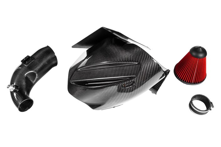
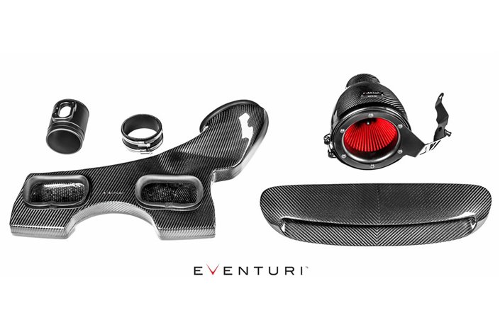
The Eventuri B58 intake system is made up of a series of components designed to perform a specific purpose and manufactured to the highest standards. Here are the details for each component and the design ethic behind them:
Each intake system consists of:
Carbon intake housing assembly
The filter housing consists of a high-flow filter, an aluminum cap, a laser-cut bracket, a carbon heat shield and the carbon pod itself, which extends to incorporate the MAF sensor and turbo pipe. The carbon pod wraps around the reverse-mounted filter and gently shapes the airflow to the integrated MAF intake pipe. This smooth reduction in cross-sectional area is reminiscent of the Venturi effect where the airflow accelerates while maintaining laminar conditions. It can be thought of as a large velocity stack - below is a diagram to show how our patent-pending design compares to a typical intake system. The carbon filter housing and inlet tube have been integrated to be one continuous piece. This reduces the number of internal interfaces and allows for smoother airflow to the turbo. The tube diameter transitions smoothly from the required diameter at the MAF sensor end to the larger diameter of the turbo inlet. More details on the patent-pending housing can be read on the Technology page.
Thermal hood in carbon
The carbon filter housing is coupled with a carbon heat shield and an additional aluminum shield that prevent the convective heat of the exhaust manifold from saturate the filter. This, combined with our full dual layer heat shields, combine to provide a very effective cold area around the filter opening.
Carbon Fiber Suction Scoop
The scoop is designed for maximum efficiency in directing incoming air into the stock duct openings. Many aftermarket scoops have a large flat area that is nearly perpendicular to the incoming air, which is not ideal for directing air into the ducts as the airflow only "hits" this flat area and creates turbulence.
The Eventuri scoops have been designed to sit directly behind the front grilles to capture as much air as possible and with a continuous curve at the duct opening to ensure this airflow is efficiently channelled. The following video explains the design features behind our M2 scoop which directly apply to the B58 scoop. Having an effective cold air feed to the filter is an essential part of our design. The presence of heat shields alone would result in high intake air temperatures, as the engine bay gets hot, especially on this engine, as the manifold is located right next to the intake.
Main heat shield
Much attention has been placed on the heat shield since the intake is next to the exhaust manifold. For this we used a dual layer primary shield with a silver finish on the exhaust side and black on the intake side. The silver layer reflects radiant heat from the exhaust and the black layer absorbs radiant heat on the inlet side. The air gap between the two layers acts as an insulator to prevent conductive heat from spreading to the inner layer. The secondary shield can also be seen in the photo above behind the turbo inlet pipe. During testing we experienced a temperature drop of over 90 degrees C across the shield which can be clearly seen in the thermal imaging video below. The effectiveness of the shield results in low inlet air temperatures during motion.
Secondary heat shield
The final shield mounts over the exhaust manifold and wraps around to protect the turbo inlet from direct heat saturation. Similar to the main shield, this is another dual layer setup with a silver layer on the exhaust side and a black layer on the inlet side. of the inlet tube.< /span>

Data sheet